PTFE-Lined Steel-Backed Bushings (SF-1 type)
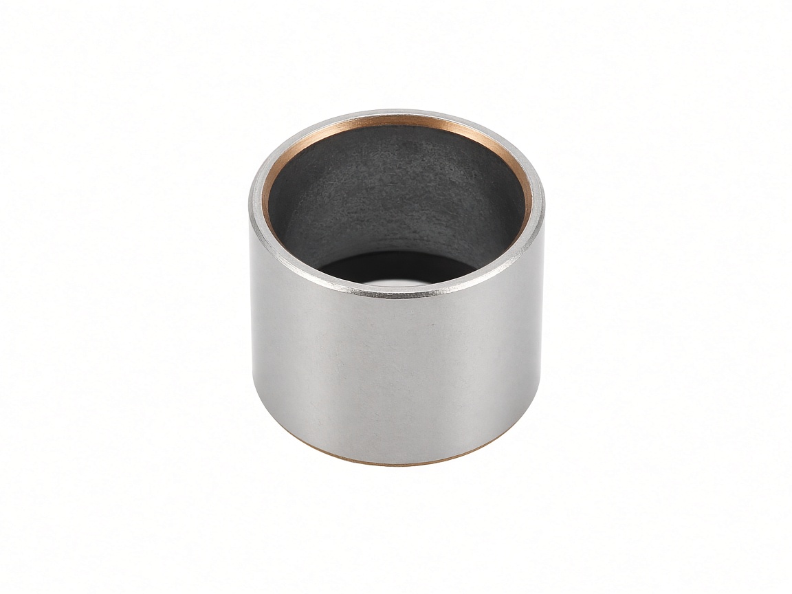
PTFE-lined composite bushings (SF-1 type) are a metal-polymer stack: steel backing, sintered bronze interlayer, and a PTFE-rich working surface. Built for dry or sparsely lubricated running with low friction at medium to higher sliding speeds — a different duty from graphite-plugged bronze or grease-pocket POM.
When to use
- Dry running or minimal lubrication preferred
- Low friction and smoother start-up than many bronze-only sleeves
- Medium to higher speed within the composite envelope
- Compact steel-backed wall where space is tight
Not the first pick when: extreme impact and heavy slow pin duty in abrasive dust with thick-wall bronze preference — graphite-plugged or wrapped bronze may fit better; or heavy slow grease-pocket duty — see POM SF-2.
Forms available
- Cylindrical (sleeve) bushings
- Flanged bushings
- Thrust washers
- Strip / plate / flat forms (where tooling allows)
- Common SF-1 type reference size ranges on request
Materials
Layer stack (typical): steel backing + sintered bronze + PTFE working layer. Exact face formulation confirmed on RFQ.
Typical duty
Hydraulic cylinder guide bushes; pump and valve sliding elements; packaging-machine cams and rotary joints; equipment pivots that should stay clean with little oil; OEM positions specified as SF-1 type / PTFE composite equivalents.
Operating envelope (qualitative)
Dry or sparse lube · low friction · medium–higher speed relative to solid-lubricant bronze. Temperature limits depend on PTFE face and duty — request factory datasheet with your RFQ.
Replacement / equivalent note
Often cross-referenced as SF-1 type (PTFE composite). Industry codes are for engineering cross-reference only. Liantuo Bushing is not affiliated with third-party brand owners.
Request a quote
Include d / D / L (or drawing), quantity, load & motion, temperature, medium, and shaft hardness if known. We usually reply within one business day.
Related
Common metric sizes (industry catalogs)
Industry-typical SF-1 type metric sizes from open manufacturer catalogs (mm). Not a row-by-row extract of any national standard. Wrapped bushings are sized for the installed bore after press-fit into an H7 housing — confirm with the factory chart.
SF-1 cylindrical — common metric series
Industry-typical fits (catalog notes): shaft often f7; housing H7. Length tolerance often about 0/−0.40 mm. Wall steps with diameter (≈1 mm small, ≈3 mm from d20, ≈5 mm large).
| d (mm) | D (mm) | Common L (mm) | Example part nos. |
|---|---|---|---|
| 6 | 8 | 6, 8, 10 | 0606 … 0610 |
| 8 | 10 | 6, 8, 10, 12, 15 | 0806 … 0815 |
| 10 | 12 | 6, 8, 10, 12, 15, 20 | 1006 … 1020 |
| 12 | 14 | 6, 8, 10, 12, 15, 20, 25 | 1206 … 1225 |
| 14 | 16 | 10, 12, 15, 20, 25 | 1410 … 1425 |
| 15 | 17 | 10, 12, 15, 20, 25 | 1510 … 1525 |
| 16 | 18 | 10, 12, 15, 20, 25 | 1610 … 1625 |
| 18 | 20 | 10, 12, 15, 20, 25 | 1810 … 1825 |
| 20 | 23 | 10, 12, 15, 20, 25, 30 | 2010 … 2030 |
| 22 | 25 | 10, 12, 15, 20, 25, 30 | 2210 … 2230 |
| 25 | 28 | 10, 12, 15, 20, 25, 30, 40, 50 | 2510 … 2550 |
| 30 | 34 | 12, 15, 20, 25, 30, 40, 50 | 3012 … 3050 |
| 35 | 39 | 12, 15, 20, 25, 30, 40, 50 | 3512 … 3550 |
| 40 | 44 | 12, 15, 20, 25, 30, 40, 50 | 4012 … 4050 |
| 45 | 50 | 20, 25, 30, 40, 50 | 4520 … 4550 |
| 50 | 55 | 20, 30, 40, 50, 60 | 5020 … 5060 |
| 60 | 65 | 30, 40, 50, 60, 70 | 6030 … 6070 |
| 70 | 75 | 40, 50, 60, 70, 80 | 7040 … 7080 |
| 80 | 85 | 40, 50, 60, 70, 80, 100 | 8040 … 80100 |
| 90 | 95 | 40, 50, 60, 80, 100 | 9040 … 90100 |
| 100 | 105 | 50, 60, 80, 115 | 10050 … 100115 |
| 120 | 125 | 60, 80, 100 | 12060 … 120100 |
SF-1 — frequently requested sizes
| Part no. | d (mm) | D (mm) | L (mm) |
|---|---|---|---|
| SF-1 0606 | 6 | 8 | 6 |
| SF-1 0608 | 6 | 8 | 8 |
| SF-1 0610 | 6 | 8 | 10 |
| SF-1 0808 | 8 | 10 | 8 |
| SF-1 0810 | 8 | 10 | 10 |
| SF-1 0815 | 8 | 10 | 15 |
| SF-1 1010 | 10 | 12 | 10 |
| SF-1 1015 | 10 | 12 | 15 |
| SF-1 1020 | 10 | 12 | 20 |
| SF-1 1210 | 12 | 14 | 10 |
| SF-1 1215 | 12 | 14 | 15 |
| SF-1 1220 | 12 | 14 | 20 |
| SF-1 1225 | 12 | 14 | 25 |
| SF-1 1515 | 15 | 17 | 15 |
| SF-1 1520 | 15 | 17 | 20 |
| SF-1 1525 | 15 | 17 | 25 |
| SF-1 1615 | 16 | 18 | 15 |
| SF-1 1620 | 16 | 18 | 20 |
| SF-1 1625 | 16 | 18 | 25 |
| SF-1 2015 | 20 | 23 | 15 |
| SF-1 2020 | 20 | 23 | 20 |
| SF-1 2025 | 20 | 23 | 25 |
| SF-1 2030 | 20 | 23 | 30 |
| SF-1 2520 | 25 | 28 | 20 |
| SF-1 2525 | 25 | 28 | 25 |
| SF-1 2530 | 25 | 28 | 30 |
| SF-1 2550 | 25 | 28 | 50 |
| SF-1 3020 | 30 | 34 | 20 |
| SF-1 3030 | 30 | 34 | 30 |
| SF-1 3040 | 30 | 34 | 40 |
| SF-1 3050 | 30 | 34 | 50 |
| SF-1 3520 | 35 | 39 | 20 |
| SF-1 3530 | 35 | 39 | 30 |
| SF-1 3550 | 35 | 39 | 50 |
| SF-1 4020 | 40 | 44 | 20 |
| SF-1 4030 | 40 | 44 | 30 |
| SF-1 4040 | 40 | 44 | 40 |
| SF-1 4050 | 40 | 44 | 50 |
| SF-1 5030 | 50 | 55 | 30 |
| SF-1 5040 | 50 | 55 | 40 |
| SF-1 5050 | 50 | 55 | 50 |
| SF-1 5060 | 50 | 55 | 60 |
| SF-1 6040 | 60 | 65 | 40 |
| SF-1 6050 | 60 | 65 | 50 |
| SF-1 6060 | 60 | 65 | 60 |
| SF-1 8050 | 80 | 85 | 50 |
| SF-1 8080 | 80 | 85 | 80 |
| SF-1 80100 | 80 | 85 | 100 |
| SF-1 10050 | 100 | 105 | 50 |
| SF-1 10080 | 100 | 105 | 80 |
SF-1F flanged — common examples
| Part no. | Shaft d (mm) | D (mm) | Flange OD ≈ (mm) | L (mm) |
|---|---|---|---|---|
| SF-1F 08055 | 8 | 10 | 15 | 5.5 |
| SF-1F 08075 | 8 | 10 | 15 | 7.5 |
| SF-1F 10070 | 10 | 12 | 18 | 7 |
| SF-1F 10090 | 10 | 12 | 18 | 9 |
| SF-1F 12070 | 12 | 14 | 20 | 7 |
| SF-1F 12090 | 12 | 14 | 20 | 9 |
| SF-1F 12120 | 12 | 14 | 20 | 12 |
| SF-1F 20115 | 20 | 23 | 30 | 11.5 |
| SF-1F 20165 | 20 | 23 | 30 | 16.5 |
| SF-1F 20215 | 20 | 23 | 30 | 21.5 |
| SF-1F 25115 | 25 | 28 | 35 | 11.5 |
| SF-1F 25165 | 25 | 28 | 35 | 16.5 |
| SF-1F 25215 | 25 | 28 | 35 | 21.5 |
| SF-1F 30160 | 30 | 34 | 42 | 16 |
| SF-1F 30260 | 30 | 34 | 42 | 26 |
| SF-1F 40260 | 40 | 44 | 52 | 26 |
| SF-1F 40400 | 40 | 44 | 52 | 40 |
Common metric sizes (industry catalogs). Part coding is typically SF-1 + d + L (e.g. SF-1 2020 = d20 × D23 × L20). Availability varies — send d / D / L (or drawing) with your RFQ. Final acceptance is per contract drawing and inspection.